

In this section, the DHC model is presented. This proposed model features innovative structures for blocks and chains that enhance the scalability, trustworthiness, and lightweight of the blockchain. These structures significantly reduce the storage requirements for both off-chain and on-chain data while ensuring the integrity of healthcare information across both chains. Furthermore, the model includes solutions to expedite healthcare data retrieval and uphold privacy through the use of smart contracts and proposed block structures.
The DHC model encompasses various components, including hospitals, wards, databases, local dynamic blocks, global blocks, ready blocks, local dynamic chains, a ready queue, a global chain, and smart contracts. Roles for patients and physicians are integral to the model, as depicted in Fig. 3.
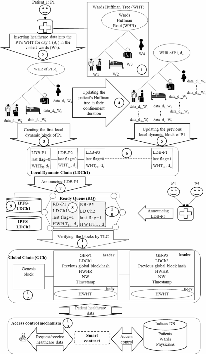
Components of the proposed model and their interactions.
As illustrated in Fig. 3, the proposed model consists of multiple hospitals where patients may visit different wards. To facilitate the organized and compact storage of patient healthcare data, a new Local Dynamic Block (LDB) structure based on a Huffman Tree (HT) is proposed. Each ward is assigned a specific weight in the HT to store its patients’ data, resulting in the creation of a Wards Huffman Tree (WHT) (1). This WHT is established to store the healthcare data of each patient visiting the hospital (2), followed by the creation of the corresponding LDB (3). The WHT undergoes daily updates as the patient seeks care in various wards (4), thereby generating a new LDB (5).
Additionally, the model introduces Local Dynamic Chain (LDCh) and Global Chain (GCh) to reduce the required storage space for both off-chain and on-chain data. Each hospital maintains an LDCh that comprises the patients’ LDBs generated daily (6). In the LDCh. the most recent LDB includes the updated WHT associated with a patient’s healthcare data, in ensuring that each patient’s most recent LDB contains a comprehensive record of their healthcare information during the relevant period. This design eliminates the need to store all LDBs while maintaining data integrity by retaining only the latest blocks for each patient.
Subsequently, each hospital’s LDCh communicates the most recent patient LDB for a desired period to the blockchain network for integration into the proposed GCh (7). This block is transformed into a Ready Block (RB), which contains the hash of patient’s WHT (HWHT) (8), while the raw data is stored on local IPFS servers within the corresponding cluster (9). The RB is placed in the Ready Queue (RQ) (10) and is verified through a two-layer consensus algorithm (TLC) based on Raft (11). Once validated, the block is incorporated into the GCh as a Global Block (GB) (12), which integrates the patient’s health data.
Furthermore, an access control mechanism is proposed to preserve patient privacy using the smart contracts (13), the database, and the GB structure. This mechanism not only reduces the retrieval time for patient healthcare data but also delineates access permissions for users. Thus, the DHC model features the proposed structures of LDB, LDCh, RB, RQ, GB, and GCh, along with a novel access control mechanism for storing and retrieving patient healthcare data, which are elaborated upon below.
Proposed local dynamic block (LDB) and local dynamic chain (LDCh) structures
The traditional block structure, primarily based on Merkle trees, encounters scalability issues when tasked with managing the extensive volume of patient data. The DHC model presents a new LDB structure founded on the WHT to address these challenges by reducing storage requirements and enhancing data retrieval speed. Initially, healthcare data from different hospital wards is organized within the WHT, leading to the creation of an LDB. Subsequently, each day of the patient’s hospitalization prompts an update to the existing WHT and the addition of a new LDB to the hospital’s LDCh. Consequently, at any given time, the patient’s most recent LDB encapsulates their complete healthcare data for that period. The subsequent subsections will elaborate on the proposed structures of WHT, LDB, and LDCh.
Proposed wards Huffman tree (WHT) structure
The WHT is derived from Huffman coding, a type of optimal prefix code utilized in information theory for data compression37. To construct the WHT using this coding approach, a Huffman Tree (HT) is first developed, where patient healthcare data is systematically organized based on the wards that patients visit. The process of creating the HT involves several steps. Initially, a set is formed containing multiple elements, each assigned a specific weight. The two elements with the lowest weight are selected, and their sum is added as a new element to the set. After this, the selected elements are removed from the set. This procedure is repeated by continuously selecting the two elements with the lowest weights from the remaining set and merging them into a new element until the root of the HT is established. An illustration of this process using three weights—W1 = 10. W2 = 20. and W3 = 15— is shown in Fig. 437.
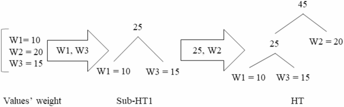
As depicted in Fig. 4, the two elements with the lowest weights, W1 = 10, and W3 = 15, are selected to form Sub-HT1. Their combined weight, 25, is then added as a new element. Next, the element W2 = 20 is merged with Sub-HT1 to form the complete HT.
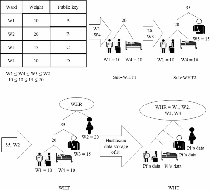
In this paper, the WHT is proposed as a modification of the HT to effectively store patient healthcare data across different wards. Upon a patient’s visit to the hospital. the DHC constructs a WHT for the patient based on the weights assigned to various wards. Each day’s patient healthcare data is systematically organized within the WHT according to the respective wards visited. The proposed WHT structure assigns greater weights to more important wards, positioning them at higher levels within the tree to facilitate faster data retrieval. The steps for constructing a patient-specific WHT are illustrated in Fig. 5.
Steps to build a patient’s WHT.
As shown in Fig. 5, the process begins with each hospital determining the weights for its wards, which are then stored in a table. Addresses for each ward are also created using a public key to further optimize healthcare data retrieval times. The wards are subsequently sorted in ascending order based on their weights. The two wards with the lowest weights, W1 = 10 and W4 = 10, are selected and designated as the leaves of Sub-WHT1. Following this, the total weight of these two wards is combined with the weight of the third ward, W3 = 15, to form Sub-WHT2. In the final step, the weight of the second ward, W2 = 20, is merged with Sub-WHT2 to create the complete WHT. The root of the WHT, referred to as the WHT Root (WHR), contains the count of wards visited by the patient (Pi). Finally, the patient’s healthcare data (Pi’s data) is stored in the corresponding relevant wards within the WHT.
Proposed local dynamic block (LDB) structure
In the context of DHC, this paper introduces a novel LDB structure aimed at locally storing data for each hospital, thereby enhancing blockchain scalability. Each patient in the hospital is associated with an LDB based on the WHT, which is updated daily throughout their hospitalization. The most recent LDB for a patient encompasses all healthcare data pertinent to the specified hospitalization period. The proposed LDB structure consists of two components: a header and a body. The header includes the following elements: patient ID (Pi), the hash of the previous LDB, WHR, a timestamp, a last flag, and a threshold value. Here, Pi refers to the unique identification of the patient, while the previous LDB hash contains the hash of the most recent LDB within the Local Dynamic Chain (LDCh), as further elaborated in the section titled “Proposed Local Dynamic Chain (LDCh) structure”.
The last flag can take on values of zero and one, a value of one indicates that the patient has been discharged, while a value of zero signifies that the patient remains hospitalized. The WHR value, outlined in the section “Proposed Wards Huffman Tree (WHT) structure” encompasses the wards to which the patient has been assigned. To support scalability, a threshold value is defined; this value indicates the maximum number of LDBs that may be generated for an individual patient during a specified period. The threshold is determined according to the average number of hospitalizations for patients in a given geographical location and initially set to zero. the threshold increases by one for each LDB generated daily. Once the number of LDBs for a patient reaches this threshold, the locally generated LDBs must be permanently stored. To ensure the permanent storage of a patient’s LDBs for a particular period, the final LDB created during that timeframe is transmitted to the blockchain network. This procedure guarantees the long-term preservation of the patient’s healthcare data, as this LDB contains the most up-to-date WHT.
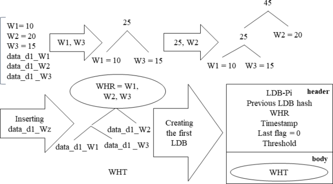
Concurrently, the establishment of the threshold serves to regulate the scalability of the LDB by limiting the maximum number of levels within the WHT. As mentioned in the “Proposed Wards Huffman Tree (WHT) structure” section, the body of the LDB houses the WHT, which is updated daily throughout the designated period. Subsequently, when the last LDB for the ongoing period is dispatched to the blockchain for permanent storage, a new WHT is generated for the initial LDB in the next period, which will also undergo daily updates during the patient’s hospitalization. Figure 6 illustrates the process of creating an LDB on the initial day of a patient’s hospitalization.
Steps for creating the LDB on the first day of the patient’s hospitalization.
As shown in Fig. 6, on the first day, a WHT is constructed for patient Pi according to the weights of wards (W1, W2, and W3) that they visit. The patient’s healthcare data for that day (data_d1_Wi) was meticulously assigned to the corresponding leaves of the WHT. This initial WHT is integrated into the body of the LDB for patient Pi’s first day, and the header includes patient ID, previous LDB hash, WHR, timestamp, last flag, and threshold value. A last flag value of zero signifies that the patient has not yet been discharged, and their subsequent LDB will be updated on the following day.
Update process of LDB: Over the course of the hospitalization period, the patient’s healthcare data is consistently updated for each day of within the patient’s WHT for each day, leading to the creation of a new LDB. Fig. 7 details the procedure for updating the LDB on the second day.
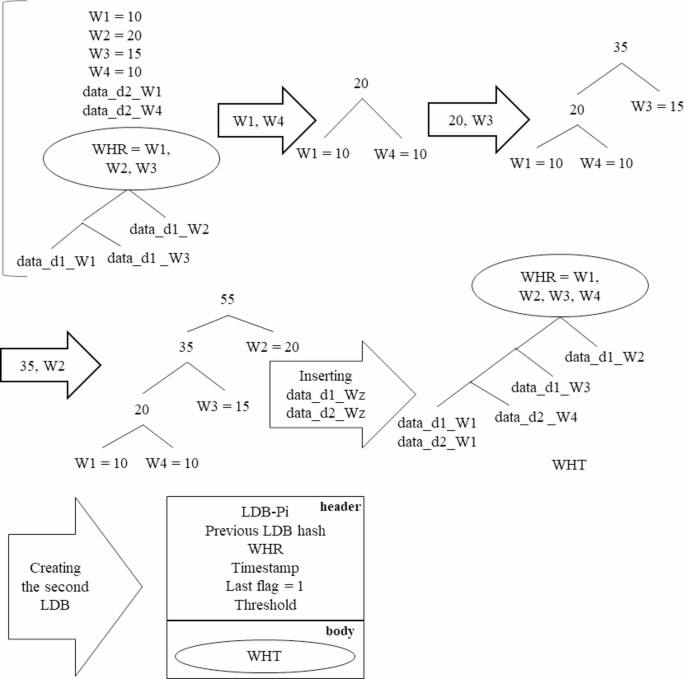
Update of the patient’s LDB on the second day of hospitalization.
As depicted in Fig. 7, the WHT for the second day is revised based on the weights of the various wards (W1, W2, W3, and W4), the healthcare data for the second day (data_d2_Wz), and the WHT of the previous day. Following this, an LDB is generated for the second day of the patient’s hospitalization. Importantly, on the second day, the last flag is set to one, indicating that this constitutes the final LDB for patient Pi’s duration of hospitalization.
Proposed local dynamic chain (LDCh) structure
Most blockchain-based healthcare models utilize off-chain storage to reduce the storage requirements for the chain of blocks. While this approach alleviates some storage issues, it often compromises data integrity and faces scalability challenges regarding local storage capacity. To address these concerns, LDCh is proposed, which ensures data integrity while optimizing storage scalability. Each hospital will implement an LDCh to store the LDBs of the patients who have received care within its facilities. This chain temporarily retains each patient’s LDBs throughout a designated period until the final LDB for that period is permanently recorded on the blockchain. The last LDB of a patient for any given period includes all their healthcare data from prior LDBs in that timeframe, which contributes to the chain’s lightweight and scalable nature, allowing it to be stored locally on fog nodes. Figure 8 illustrates the LDChs of two hospitals, showcasing the patients’ LDBs and the corresponding block announcements for permanent storage in the blockchain network.
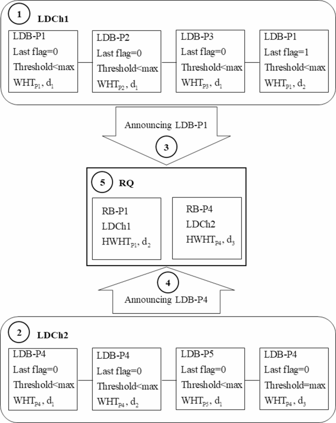
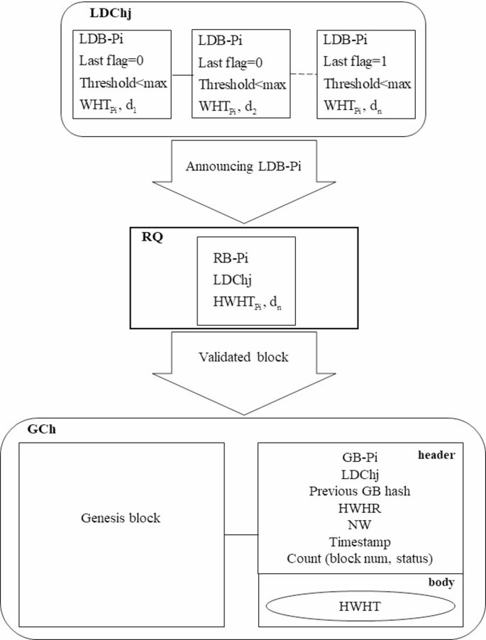
Proposed LDCh structure and the block announcement for permanent storage on the blockchain.
As depicted in Fig. 8, the LDChs of two hospitals (LDCh1 and LDCh2) consist of LDBs associated with various patients Pi. Both LDCh1 and LDCh2 forward their blocks to the Requests Queue (RQ) for permanent storage in the form of Ready Blocks (RBs). An LDB for patient Pi (LDB-Pi) may transition to the RB state under two conditions: (a) the last flag is set to one, indicating discharge, or (b) the threshold has reached its maximum value. On the first day, an LDB-Pi for each patient (P1, P2, P3, P4, and P5) is created in both LDCh1 and LDCh2, with the last flags set to zero, meaning none are converted to RBs (1), (2). However, on the second day, an LDB-P1 is created in LDCh1 with the last flag set to one, indicating discharge. The LDCh1 is then included in its header and submitted to the RQ as the RB for patient P1 (RB-P1) (3). In contrast, on the third day, LDB-P4 in LDCh2 reaches the maximum threshold value, prompting LDCh2 to announce it as RB for patient P4 (RB-P4) (4). The RQ accepts the requests from LDCh1 and LDCh2 and places them in a First-In-First-Out (FIFO) queue for validation (5). The approved blocks are subsequently integrated into the Global Chain (GCh) as Global Blocks (GBs) as detailed in the section on “Proposed Global Block (GB) and Global Chain (GCh) structures”.
Once the LDB-P4 on the third day has been converted to the RB-P4 due to exceeding the maximum threshold, additional LDBs will still be generated for patient P4 in LDCh2. For the fourth day, only the healthcare data from that day—marking the beginning of the next period—will be utilized to create the WHT. The WHT for the fourth day will not encompass data from previous days, as this data was previously with the initial RB-P4 for permanent blockchain storage. The new WHT will be updated until a second RB-P4 is announced to the RQ, enabling the formation of subsequent LDBs for patient P4 in the following days of the second period. The WHT is the fourth day not the previous days, this data was sent to RB-P4 for permanent storage. The new WHT is updated until a second RB-P4 is announced to the RQ. After the second RB-P4 is announced, a new WHT will be developed for the creation of LDB-P4 in the third period. This iterative process will continue until the final RB-P4 is submitted to the RQ. This method preserves the scalability of the LDB and LDCh by generating new WHTs that exclude previously stored healthcare data.
-
Creating ready blocks (RBs): As previously discussed in the “Proposed Local Dynamic Chain (LDCh) structure” section, during each specified period, the last LDB of a patient is converted into RB status for permanent storage on the blockchain. The LDBs created for a patient encapsulate comprehensive healthcare data from the relevant period, requiring substantial storage capacity. Hence, to maintain the RB scalability, a proposed RB block structure based on LDB is introduced, illustrated in Fig. 9.
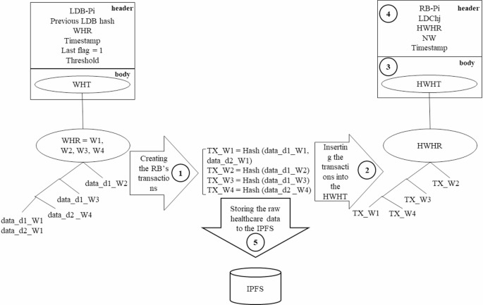
Proposed RB structure and storage of raw healthcare data in IPFS.
In Fig. 9, a hash value is generated for each ward’s healthcare data (1), which is then included in the WHT as the ward transaction (2). The new HWHT is incorporated into the body of the RB body (3), along with values for RB-Pi, LDChj, the HWHT’s root (HWHR), the number of wards visited by the patient (NW) and timestamp in the RB header (4). Here, the LDChj indicates the LDCh number from which the block was created. Additionally, IPFS servers are employed by each hospital to store the ward’s healthcare data (5).
-
LDCh trimming: To manage storage demands, many researchers resort to off-chain solutions to alleviate the on-chain storage burden of healthcare data. However, such local off-chain storage often encounters scalability issues. In this paper, the LDCh is proposed as an off-chain solution, implementing a trimming process to remove outdated blocks from the on-chain storage in each time frame to bolster scalability. The LDCh trimming process unfolds as follows:
-
a)
Patient LDBs are identified as Candidate Blocks (CBs) if their corresponding RBs have been submitted to the RQ and integrated into the blockchain as delineated in the section on “Proposed Global Block (GB) and Global Chain (GCh) structures”. All blocks not classified as candidates are labeled Non-Candidate Blocks (NCBs).
-
b)
The LDCh scans from the left until the first NCB is identified. The six blocks preceding the first NCB, along with all subsequent blocks—regardless of whether they are CBs or NCBs—remain in the chain, while the other CBs are purged from the LDCh. This trimming procedure ensures block integrity, borrowing principles from Bitcoin, which maintains the integrity based on its preceding six blocks38. Therefore, in LDCh trimming, the six blocks before the first NCB are preserved in the chain. The LDCh trimming process is illustrated in Fig. 10.
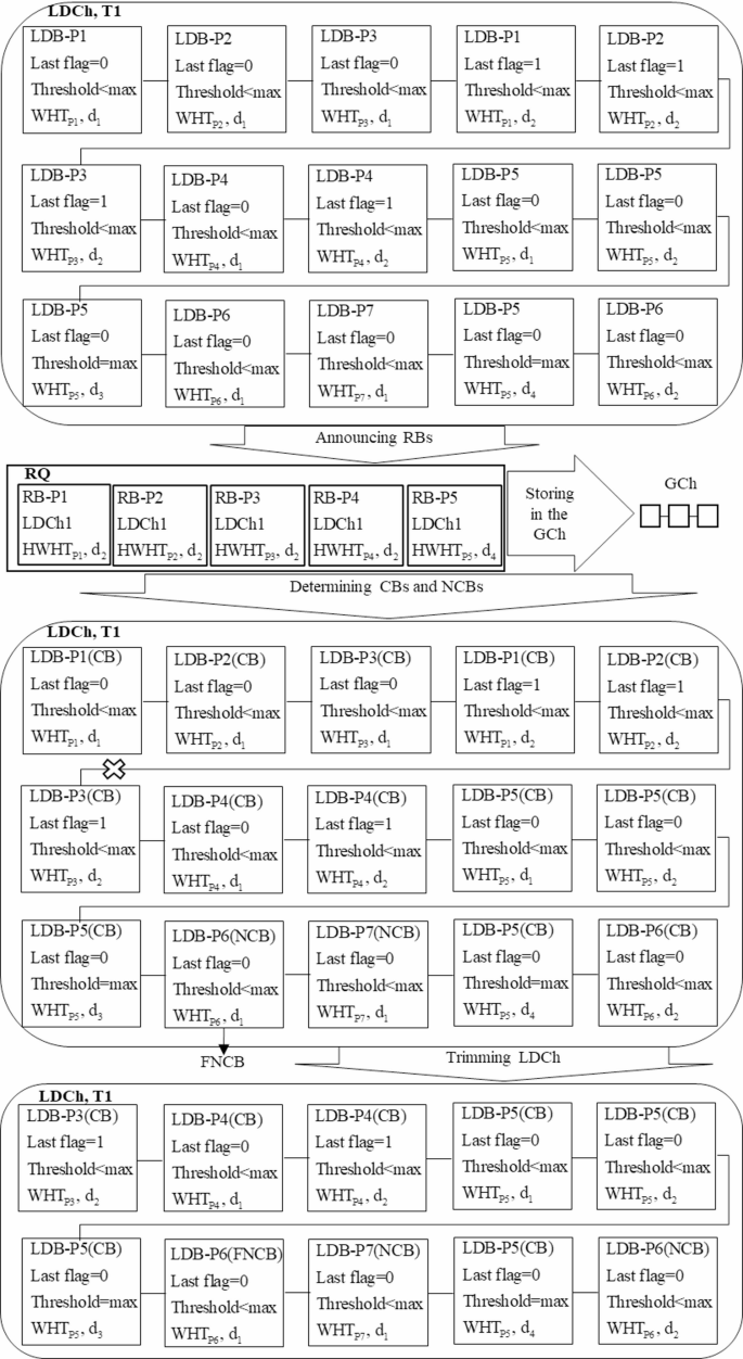
Presentation of the LDCh trimming process.
As demonstrated in Fig. 10, during the timeframe T1, the LDCh generates fifteen blocks for patients P1, P2, P3, P4, P5, P6, and P7. LDB-P1, LDB-P2, LDB-P3, and LDB-P4 are formulated on the second day, while LDB-P5 is created on the fourth day, all transitioning to RB-P1, RB-P2, RB-P3, RB-P4, and RB-P5 for submission to the RQ for inclusion in the GCh.
These blocks and their associated LDBs created for these patients in previous days are classified as CBs. Conversely, LDB-P6 and LDB-P7 have not yet produced any blocks in a ready state, categorizing them as NCBs. Upon scanning from the left side of DLCh, LDB-P6 emerges as the first NCB (FNCB). Consequently, the six preceding blocks, even if they are CBs, cannot be deleted and will remain within the LDCh. Additionally, LDB-P5 and LDB-P7, which follow FNCB, are retained in the LDCh, regardless of their status as CBs or NCBs. By eliminating other CBs, the length of the LDCh is effectively reduced from fifteen to ten. Therefore, the trimming of the LDCh in each timeframe promotes off-chain scalability, contrasting with other methods proposed in existing research that struggle with adequate storage space.
Proposed global block (GB) and global chain (GCh) structures
In blockchain-based healthcare models, researchers typically utilize on-chain storage for the permanent retention of blocks. This on-chain framework is often complemented by off-chain solutions to enhance the scalability and manage the storage demands of healthcare data. Consequently, simultaneous access to both on-chain and off-chain data is necessary for effective data retrieval. This paper proposes a Global Chain (GCh) as an on-chain solution that stores global blocks (GBs) containing comprehensive patient healthcare data over specific time periods. Although the GCh uses off-chain storage for healthcare data, retrieval is solely accomplished through access to the GCh itself, thereby reducing data retrieval times. The architectural framework of the proposed GB and GCh is illustrated in Fig. 11.
The proposed GB and GCh structures.
As depicted in Fig. 11, once the LDB-Pi is transformed into an RB-Pi, it is transmitted to the blockchain network for verification. Upon successful verification, the RB-Pi is incorporated into the GCh as a GB corresponding to the patient Pi (GB-Pi). The GB structure comprises two components: a header and a body. The header includes the patient identification number (Pi), the LDCh number of the hospital where the RB-Pi was created (LDChj), the previous GB hash, the HWHT root (HWHR), the number of wards visited by the patient (NW), the discharge timestamp, and Count, which is an ordered pair (block num, status) that links all GBs related to the patient during their hospital stay.
Utilizing the Count attribute allows for efficient access to each GB associated with a patient in an O (1) time complexity, through recursive referencing using the block num of the most recent GB-Pi. The block num reflects the sequence of the last GB-Pi added to the GCh. If the status value in the last GB-Pi equals one, it indicates the conclusion of the Pi’s hospitalization, allowing for full access to their healthcare data from that period. Conversely, if the status value indicates that the patient’s treatment is ongoing; their healthcare data will be appended to the GCh upon completion. Detailed procedures for retrieving healthcare data from the GCh using the Count attribute will be outlined in the “Proposed access control mechanism” section.
The body of the GB comprises the latest updated hash values of the WHT leaves (HWHT) for the patient during the specified period. The GBs from various hospitals are incorporated into the proposed GCh, which is stored across distributed nodes. The process of creating a patient transaction and its subsequent inclusion into the GCh is illustrated in Fig. 12.
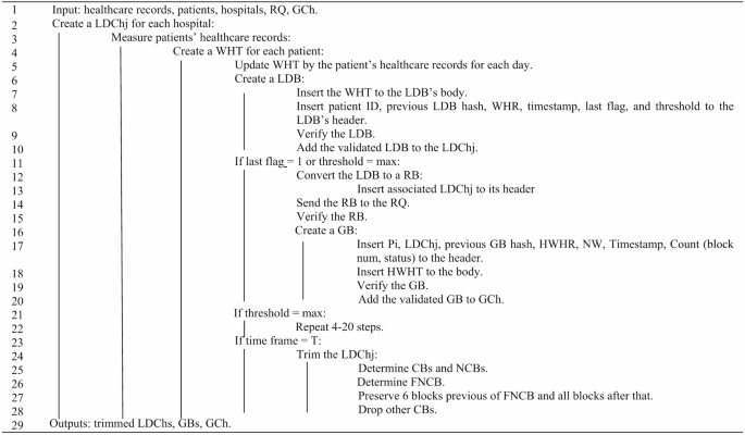
Pseudocode for creating LDB, LDCh, GB, and GCh.
Proposed two-layer consensus (TLC) protocol
This paper presents a two-layer consensus protocol designed to increase throughput, reduce execution time, and reduce energy consumption. The proposed consensus protocol verified blocks through two distinct layers, local and global. In each hospital, LDBs are verified locally, while GBs are verified globally across all hospitals.
During each consensus round in the local layer, each hospital identifies several trustworthy fog nodes that have recently been authenticated by the hospital’s internal network to serve as participating nodes in the consensus process. These trustworthy nodes then vote to elect a leader using the Raft protocol39 and verify the generated LDBs locally. Once an LDB is transformed into an RB, the global consensus layer is activated to validate the RB. In this layer, the leader nodes from the local consensus layer are recognized as trustworthy nodes and introduced to the blockchain network. These nodes engage in a voting process within the global consensus layer, also utilizing the Raft protocol to select a global leader, followed by the verification of the RB. The validated RB is subsequently added to the GCh as a GB.
The adoption of a two-layer consensus protocol enables local verification of LDBs by nodes within each hospital, which increases the throughput and reduces the execution time. Additionally, each hospital incorporates several trustworthy nodes from its private network to participate in the consensus, thereby increasing the overall trustworthiness of the model. Furthermore, since LDBs are verified locally and independently in each hospital—with only a limited number submitted for global verification—both energy consumption and execution time are reduced. The pseudocode for the two-layer consensus model is illustrated in Fig. 13.

Pseudocode for the two-layer consensus protocol.
Proposed access control mechanism
Ensuring patient privacy is a critical challenge in blockchain-based healthcare data storage and retrieval models, a concern that traditional blockchains fail to sufficiently address. Additionally, the data retrieval time in traditional blockchains is linear, exhibiting O(n) complexity, which negatively impacts efficiency in healthcare contexts. Many blockchain-based models employ complementary solutions, such as smart contracts (SCs), to protect user privacy and reduce data retrieval times. Consequently, this paper presents an access control mechanism aimed at safeguarding patient privacy while enhancing the efficiency of healthcare data retrieval. The proposed mechanism utilizes the GB structure, SCs, an indices database (IDB), and local IPFS servers to facilitate timely access to patient healthcare data while preserving their privacy. The steps involved are detailed as follows:
First step: creating a indices database
The first step in the proposed access control mechanism involves establishing an IDB to organize healthcare data. The IDB includes tables of patients, physicians, and wards, as displayed in Fig. 14.
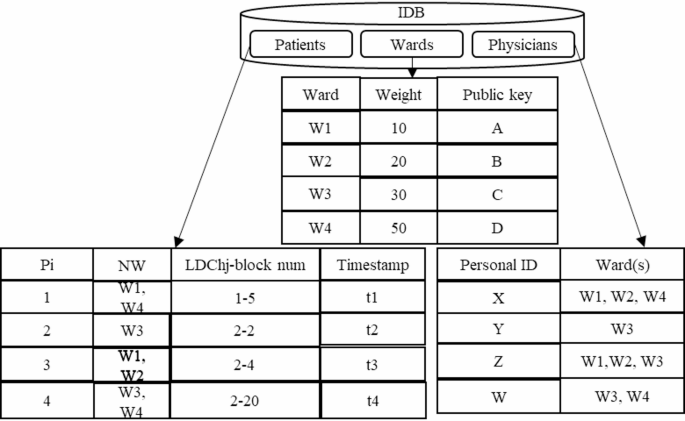
As illustrated in Fig. 14, the IDB comprises three tables for storing data related to wards, patients, and physicians, described below:
-
Patients table: This table records the hospitalization history of patients, designated by the identifier (Pi), with the NW indicating the wards in which each patient received treatment. Given that a patient may be hospitalized in multiple facilities, leading to the creation of several GBs in the GCh during each hospitalization period, the table also includes Timestamp and LDChj-block num attributes. These features facilitate more efficient healthcare data time retrieval. The LDChj-block num denotes the most recent GB allocated to the patient during their hospitalization at each hospital, ensuring that as new GBs are created, the patients table is updated accordingly. By utilizing the LDChj-block num in the patients table and the Count (block num, status) in the proposed GB structure, patient healthcare data can be retrieved in O(1) time, compared to O(n) retrieval time in traditional blockchains.
-
Wards table: Initially, a private-public key pair is generated for each ward by the SC. Subsequently, a weighting is assigned to each ward based on its priority in the treatment process; this information, along with the ward’s public key, is recorded in the ward’s table.
-
Physicians table: This table outlines the access control level of physicians concerning the wards. It includes identifiers for physicians, represented by personal IDs, along with the number of wards to which they have access.
Second step: determining access control level of physicians
-
Following the creation of the IDB, the proposed access control mechanism establishes the access control level of physicians to healthcare data to protect patient privacy through the following procedure: Physicians are first authenticated by the SC. Each physician then generates a signature script using the public keys of the wards they are authorized to access, as outlined in Eq. (1).
$$sign(hash(pubke{y_{W1}}),hash(pubke{y_{W2}}),…,hash(pubke{y_{Wn}}))$$
(1)
Physicians insert the hashed public key of the accessible wards into Eq. (1) and sign the script with their private key. They then submit this signed script to the SC, requesting access to the healthcare data of patient Pi.
-
The SC references the patients table to obtain the Timestamp and LDChj-block num values associated with the GB of patient Pi and retrieve the corresponding blocks from the GCh.
-
The desired healthcare data from the relevant ward is then fetched by the SC using the HWHT and transmitted to the physicians.
The process for physicians to access patient healthcare data is outlined in Fig. 15.
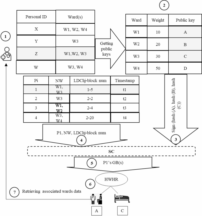
Steps for retrieving patient healthcare data for physician.
In Fig. 15, to access the healthcare data of patient P1, a physician with personal ID = Z follows these steps: (1) First, they create a digital signature according to their authorized wards; (2) they send the signature to the SC; (3) the SC retrieves the GB(s) linked to patient P_1 using the LDCh_j-block num and Timestamp in the patients table; (4) the GB body contains a HWHT for rapid access to the relevant ward data; (5) the SC retrieves the requested data from the local IPFS according to the LDCh_j value. This mechanism ensures patients privacy by enforcing access control levels of physicians and only references the GCh to fetch healthcare data, thereby reducing retrieval times. The pseudocode of the proposed access control mechanism is depicted in Fig. 16.
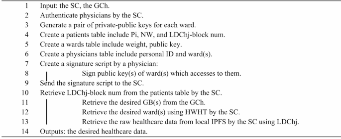
Pseudocode of the proposed access control mechanism.
Retrieving patient healthcare data from the GCh
As described in the section on “Proposed Global Block (GB) and Global Chain (GCh) structures” in a DHC system. although off-chain storage is utilized, data retrieval is executed solely through the on-chain GCh. This approach contrasts with other blockchain-based data storage and retrieval models that use both off-chain and on-chain mechanisms for data retrieval. The process of healthcare data retrieval from the GCh is illustrated in Fig. 17.
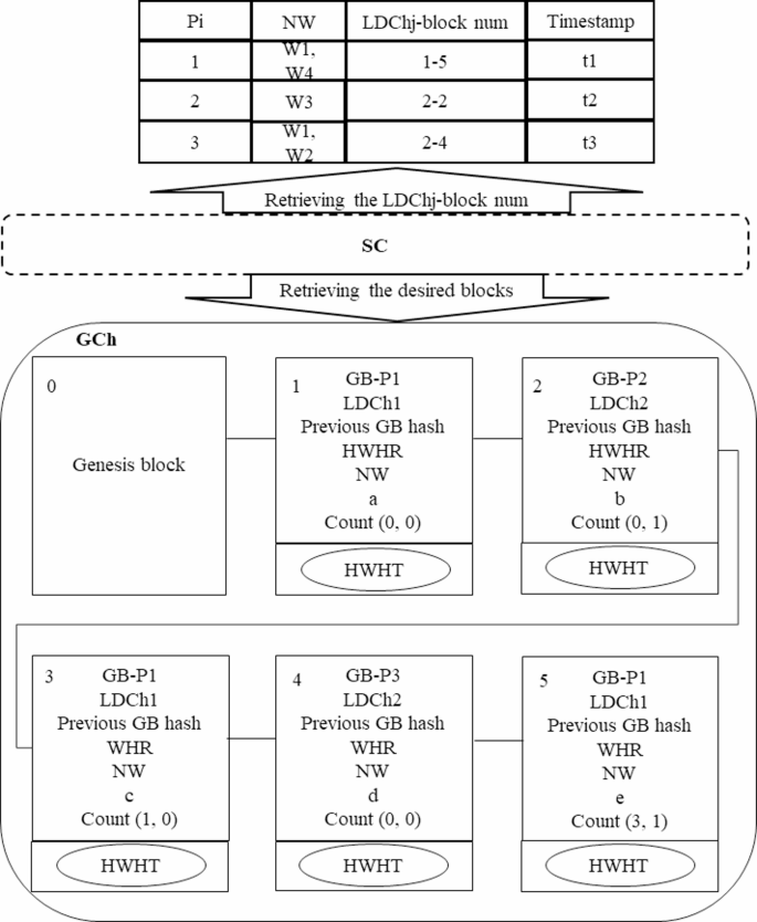
Retrieving healthcare data from GCh using the proposed access control mechanism.
To retrieve healthcare data, it is necessary for the SC to access the patient’s GB(s) and then present the required data to users according to the proposed access control mechanism. The patients table stores the latest GB(s) for each patient during their hospitalization period, identified by the LDChj-block num. As shown in Fig. 17, the SC first refers to the patients table to obtain the LDChj-block nums associated with patients P1, P2, and P3, subsequently retrieving their healthcare data as follows:
-
Retrieving GB(s) for patient P1: In the patients table, the LDChj-block num for P1 is noted as 1–5, indicating the patient was hospitalized at a facility with LDChj is 1 and the last GB recorded for this hospitalization period in the GCh is block num 5. The SC first accesses block num 5 in the GCh with an O (1) time complexity. From this block, it retrieves the Count value (3,1), which indicates two things: The status value of 1 signifies that block num 5 is the final block for P1 in this hospitalization period, meaning no further blocks will be added as the patient has been discharged. There exists at least one additional block for this patient in the GCh, specifically block num 3. The SC subsequently retrieves block num 3 with O(1) time complexity, which yields a Count value (1, 0) indicating that block num 1 is another record for P_1. The SC also accesses block num 1 in O(1) time, obtaining a Count value (0, 0). Since the block num equals 0, this indicates it is the first block of P1 recorded in the GCh for the specified hospitalization period. Therefore, the search for GBs of patient P1 concludes, retrieving all relevant blocks with O(1) efficiency.
-
Retrieving GB(s) of patient P2: The SC retrieves the LDChj-block num for P2, which is 2–2. This indicates that the block(s) of the patient was introduced to the GCh by the hospital with LDChj = 2. The SC retrieves this block in O(1) time, yielding a Count value (0,1), suggesting that this is the final block for P2 during their hospitalization since the status is 1. Block num “0” indicates that there are no additional blocks for this patient during the hospitalization period, which concludes the retrieval process.
-
Retrieving GB(s) of patient P3: The LDChj-block num for P3 is recorded as 2–4, which the SC retrieves from the GCh in O(1) time. The resulting Count value (0,0) indicates that P3 has not yet been discharged, and further blocks are anticipated to be added to the GCh in the future. The block num being 0 signifies that this is the initial block for P3 in this particular hospitalization period, effectively concluding the search, as there are currently no other blocks for P3 in the GCh.
After successfully retrieving the relevant GB(s) for each patient, the SC proceeds to access the necessary ward data using the physicians’ signature script.
link